

My Rocketry Project
My passion for engineering originated from watching SpaceX's Falcon 9 rockets and their self-landing feature. After saving enough money to buy a 3D printer, I decided that I'd put myself to the challenge of designing and fabricating a reusable F-class rocket capable of reaching at least 1000 feet with an onboard automatic parachute system.
Parachute System
My initial parameters for this system were that it had to operate autonomously and electronically. After discussing with friends and forums, I decided to go with a gyroscope sensor that would set off the parachute once it rotated a certain direction. Here in the video, you can see that after rotating the rocket at around 90 degrees the parachute ejects. This was probably my favorite section because of how strictly creative making this was.

Here is the assembly of the electronic component of the parachute system in its most basic form. The system consists of an Arduino, servo motor, gyroscopic accelerometer, and a 9-volt battery. Once activated the servo will rotate and unlatch a rubber band that will release the nose cap and ultimately the parachute.
The video on the left shows the proof of concept of the electronic system. The Arduino is coded so that the servo turns when the orientation of the sensor is tipped over 90 degrees in any direction. Because the MPU 6050 (gyroscopic sensor) activated prematurely due to heavy acceleration or jerking, a digital filter was needed to refine any sudden movements.
The next step knowing that the system was feasible was to model the electronic bay. I designed the electronics bay to securely house any electronics without the use of glue and have enough room for wires. I did this by making grooves to fit rubberbands and precisely dimensioning holders that would fasten devices. After many iterations, designs, and PLA I modeled the final version of the electronics bay shown below.
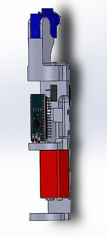


Here you can see how the servo is connected to the nose cone and the rubber band that is elastically loaded to deploy the nose cone. As well as how the entire electronic bay sits in the rocket.
The nose cone that holds the parachute is designed so that it would secure the chute until deployed. It contains holes at the bottom for the servo to latch to and a rubber band is attached to the opening to launch the chute forward. The rubberband implementation was to ensure that the parachute would deploy in any direction the nose cone is in. In the video you can see that once deployed, the chute is thrown forward.

Propulsion
The propulsion of the rocket consisted of the propellant, motor, and nozzle. For this section, I chose to do a solid rocket motor as it was most practical. From research, I decided between two propellant combinations. Potassium Nitrate/sucrose and Potassium Nitrate/sorbitol. The ladder was chosen due to its ease of manufacturing and safety. The nozzle was designed as a diverging bell nozzle and made with an amateur rocket endorsed concrete powder. I chose a diverging nozzle because the flow velocity was over Mach 1. This meant that a converging and diverging nozzle was not needed.


To cast the fuel, the Potassium nitrate and sorbitol are finely mixed with a blender. This is then heated on an electric stove until the mixture is putty-like. Using the same rod and dowel method as before I press down to make sure there are no pockets of air in the grain. On the left, you can see the mixture turning from a powder to a solid as well as the cross-section of the motor.


The right shows the concept for making the nozzle. The bottom semi-sphere shape forms the nozzle, as I pour the concrete/water mix into the (red) motor I periodically press it down with another 3D printed PLA dowel.
I chose three different designs for a fuselage. A fully 3D printed fuselage, A cardboard tube, and a dowel with ring formers. Because this rocket won't experience much bending, axial, or torsion, the only factors I was looking for were ease of manufacturing, weight, and printing time.
Using motor calculators and software I am able to solve chamber pressure and impulse as a function of throat diameter. I initially chose a throat diameter from an ideal expansion ratio and increased or decreased from there. After picking the top three optimized combinations it was time for testing.
For performance and testing, I originally coded a script that would record thrust over time from a strain gauge but I could not get my hands on a strain gauge. Instead, I 3D printed a motor mount that would securely fit the motor and fastened it onto an analog scale. Using slow-motion recording I was able to graph the pound-force over time and calculate for total impulse.
.jpg)
Fuselage and Stability
The fuselage includes the body, motor mount and, tube. This section is extremely important as it dictates the stability of the plane by optimizing the center of mass and pressure.
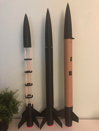
Figure 1: cardboard, nose cone, and a motor mound
Figure 2: ring formers, nose cone and motor mound
Figure 3: entirely 3D configuration

here is a scoring matrix for the types of fuselages
As you may have noticed, the fins of the rocket look less and less ridiculous as I went from my first design (figure 3) to my final design (figure 1). This is because of the rocket's aerodynamic stability. A rocket is stable when the center of mass is above the center of pressure exactly one tube diameter. Because the center of mass is different in every design, in order to keep the center of pressure as low as possible I had to sweep the fins as far as possible.


This is a software called Openrocket that lets me calculate for the center of mass and center of pressure. This rocket has a stability of 1.57.
Here is a stability test flight for a rocket I designed with a stability of 1.32.