

Electric Skateboard Project
Ever since high school skateboarding and engineering have been my favorite hobby and interest, so I decided a good way to combine these two things is to create my very own electric skateboard. Here you will learn more about my engineering/skateboarding lovechild that I am PROUDLY too scared to ride.
First Test Run! Works great!
The theoretical max speed is 23 mph, but trying to confirm that on 4 tiny wheels is troublesome, and frankly, dangerous!!!! Here is my friend attempting to reach max speed while sitting down to not get hurt. Helpful tip: sitting down does not help at all! To this day I have yet to confirm the top speed! I take this as a good sign as my ability to ride a skateboard has yet to reach my ability to engineer.
Version 1
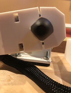
The motor mount needed to be able to withstand the static and dynamic forces of the one-kilogram motor while riding the skateboard. My initial design consisted of a near-perfect cut-out of the truck cross-section, as well as a nut and bolt to tighten the entire mount.
How the motor mount gets tightened.
Motor Mount


You can see the finite element analysis of the version one motor mount, including the maximum dynamic load from the motor and skateboard. To see the rough calculations on how I derived the dynamic force, click on "Force Calculation" on the right.
This version of the mount failed when performing a drop test and cracked at the stress concentration shown on the right. I suspect that I tightened the screw too much for the brittle behavior of the PLA material to handle. This observation directed me to my second design idea.

Version 2
Knowing the brittle behavior of PLA, I decided to design the mount so that all stress would act through machine screws right where the stress concentrates. The FEA of this design shows much less stress around the trucks and eliminates unnecessary stress concentration. It directs all stress on the steel screws and not the PLA.

Note that the PLA is not only tapped for the machine screws to fit in but there is also a nut that secures the end of it. The picture below shows the cutout of the nut to constrain while screwing.
Enclosure

Designing the enclosure was a simple and fun task. Its main purpose is to house the electronics and battery with sufficient protection to the battery. My main challenge in building this component was to make the enclosure bottom as flush as possible with the skateboard, to ensure the screw would pass through the skate deck and enclosure mounting plate perpendicularly, and to reduce 3D printing times by also reducing the amount of material used. The result was a 2 piece 27 hour 3D printed enclosure.
In order to have the enclosure plates flush with the curved skateboard, I modeled skinny testing prints that would reflect the enclosure bottoms and checked to see how level it was. Below are pictures of two test prints, one that wasn't level and one that was.


To reduce printing times I cut material where it wasn't needed. For example, the mounting plates were originally linear plates, but the final product has the edges cut out. Shown below is the original version and final version, respectively.


Nuts and bolts are used to clamp the enclosure to the skateboard. I designed the enclosure plate to perfectly match the nut to omit the use of a hex nut driver. To do this I first measured the dimensions of the nut with a caliper and prototyped using CAD and my 3D printer. Below are the nut and bolt prototypes. This made ease of accessibility ridiculously better as the only tool that is needed is a screw driver.

.jpg)
.jpg)
The finished enclosure!
Electronics
_edited_edited.jpg)
The electric components of this build were chosen with a big influence on price and performance.
Once electrical components have been finalized, the VESC is set to be programmed for battery and motor specifications.
Electric testing was done by using a BLDC tool to test the current and voltage at a given throttle percentage.